Friday, March 26, 2010

Don't Miss: PMPA National Technical Conference: Apr. 24 - 27

The Precision Machined Products Association (PMPA) will host its annual Tech Conference this year in Pittsburgh, Pennsylvania April 24-27. As is usually the case, the PMPA has the event packed full with valuable sessions for members and non-members alike. Sessions of special interest include Thread Milling & Thread Whirling 101, by REM Sales' own Dan Murphy, and the Competing Process Forum. Technical members, including REM Sales, are available to meet with attendees throughout the show. For more information: http://pmpa.org/meetings/techconf/

Quick Links:

>> Program Overview: http://pmpa.org/meetings/techconf/program.html

>> Sessions and Speakers: http://pmpa.org/meetings/techconf/sessions.html

>> Registration: http://pmpa.org/meetings/techconf/registration.html

Wednesday, March 24, 2010

Reduce Part Costs With Simple Automation

The Swiss Wizard: Reducing Part Costs – Part I – Direct Labor and Simple Automation
By Dan Murphy

This article is Part 1 of a Swiss Wizard series on Reducing Part Costs and focuses on labor and simple automation to hold down costs…

Customers will stop buying from you for a variety of reasons including: service, delivery, their perception of your responsiveness, quality, and price.

When the economy gets ugly, many buyers naturally focus on price. China and other low labor cost countries open the selling conversation with price,. Reducing your high cost of business (compared to low labor countries) becomes the critical component of staying competitive… and getting the business.
Your high costs open the door for foreign competitors. And while they focus on price, they also may deliver quality, service, and good value. Don’t assume that foreign competitors can’t deliver quality- they can.

How do you beat them?

You must be zealous about reducing costs or you’ll see your customers disappear. Let's get started by looking at the factors driving the price of the parts that you are producing:

> Material – raw material for the part
> Tooling – tooling, cutting tools, collets
> Direct Labor - loading, setup, operating
> Machine Time – Setup time, cycle time, work in process inventory
> Overhead – Personnel, facilities, utilities, machine costs
> Other – Taxes, paperwork, compliance

It should come as no surprise that each bullet point above can be 'attacked' to produce cost savings. Reducing setup and changeover times are critical but have been covered extensively in previous articles in the Swiss Wizard Series. For that reason, this month's article will focus on cost savings from direct labor.

Eliminate Secondary Operations:
Doing away with secondary operations reduces direct labor costs and improves part throughput. Today's multifunction and CNC Swiss lathes are a great place to start because they're designed to produce complete parts in one operation. Removing direct labor costs will allow you to be more competitive with low labor cost countries. Remember, even small improvements can make a difference over time.

Simple Automation Produces Big Results:
Chip conveyors and automatic bar loaders are examples of simple automation that can drop thousands to your bottom line each year. If you're thinking that “it takes no more than five minutes, a few times a day, to clean out the chips, why would I buy a conveyor for each machine?” take a look at the following example.

Chip Conveyor:

> Cost: $5,000 - $7,000 per machine.

> Without it chips are pulled once an hour.

> It takes 5 minutes to pull chips. Plus it makes a mess.

> With a conveyor chips pulled one time per shift.

> 6000 hour year at 80% utilization = 4800 Hours.
4800 x 5 minutes=24,000 minutes/60=400 hours of direct labor at $20.00/hour=$8,000.00

> 4800/8=600 x 5 minutes = 3000/60 = 50 hours of direct labor at $20.00/hour = $1,000.00

> Chip conveyor savings $7,000.00 per year / per machine.

Automatic (Magazine) Bar Feeder:
Now let's take a look at the productivity increase possible of by switching from a tube feeder to a magazine bar loader, using a 2” part cut from 12' stock as an example.


Bar Length in InchesA144
Bar Usage Per PartB2
Remnant LengthC7
Parts Produced by Bar69
Cycle time in secondsD45
Bar change time for tube feeder.
Approximately 300 seconds @ 100% efficiency
600
Bar change time for magazine feeder45
Available time in hoursE20.4
Available time in seconds73,440
Total daily production with tube feeder1,366
Total daily production with magazine feeder1,609
Percent Production Increase: 17.50%

In a 5,100-hour year, a 17% production increase will result in 867 additional billable hours. At $60.00/hr that is $52,020.00 in additional income. The bar loader also will save approximately 985 hours of direct labor based on the given conditions.

Add 400 hours [for what] and multiply these hours by five machines. You'll save 6,925 hours of direct labor. Reducing these small amounts of direct labor creates large savings and allows one operator to run more machines.

Stay tuned for part II in the The Swiss Wizard's column next month: Matching the right machine with the right job.

Friday, March 19, 2010

Looking Ahead to EASTEC 2010

EASTEC 2010 will be here soon.

Scheduled for May 25-27 at the Eastern States Exposition Center in Springfield, Massachusetts, EASTEC is the largest annual manufacturing event on the East Coast. This years show will include hundreds of exhibitors and draw more than 9,000 visitors to the three day exposition.

REM Sales will display two machines in The Robert E. Morris Company booth (#1305), including a new S series machine. More information about the S205 and S206 can be found in Wednesday's post.

In addition to showcasing our machinery, REM Sales application engineers will be on hand to answer questions and discuss your requirements. The show is a great opportunity to discuss new part projects and review existing operations.

The Society of Manufacturing Engineers, the folks who host the show, have added several new features to help make your show planning easier. One of those great new features is the interactive floor plan, allowing visitors to see detailed floor maps and booth previews. They make it easy for you to add exhibitor booths to your itinerary in advance with the new show planner.

Finally, avoid the hassle of standing in long registration lines by registering online in advance.

Wednesday, March 17, 2010

New Tsugami S Series Machines Available!!

Two new 20mm Tsugami Precision Swiss Turns will be available in early April of this year. The new Tsugami S205 and Tsugami S206 were designed to provide Swiss technology users the flexibility and capability to meet a wide range of needs, at an affordable price. The truth is that Tsugami's successful "Super Swissturn" SS Series inspired development of the economic, flexible, higher rpm S205 and S206 models. Both machines are ideally suited for production of complex parts with live tools for cross and face operations on the main and sub spindle.

Users will also appreciate the FANUC 31i-A 2-path control that permits true simultaneous operation of the main and sub spindle, reducing overall cutting time. Like the SS series, the new S series also features a modular tool zone. Yes, it allows driven tools to be moved from main to sub spindle and from face to cross positions with ease. Those of you who have struggled in the past setting up smaller toolzones will really appreciate the roominess of the S series.

So, what's the difference between the S205 and the S206? The S206 has the same capabilities as the S205 but adds backworking y-axis.

If you're interested in learning more, contact your local Tsugami distributor or send us an email.

Monday, January 25, 2010

Reducing Set-Up Times on CNC Swiss

I recently had a conversation with someone who told me it wasn’t possible to change over a CNC Swiss in less than two hours. Imagine my surprise, since I was doing it daily over a quarter century ago on twin turret CNC Swiss machines that lacked some of the user friendly features that are part and parcel of today’s more modern machine.

Nowadays the subject has been studied to death. There are all sorts of programs and systems available to be studied or implemented. The internet makes learning how to become more efficient free and easy. Just type “Lean Manufacturing” or “5S” into Google and you’ll find more than 3 million hits for “lean” and over 36 million for 5S.

There are also all sorts of quick change and multifunction tooling that didn’t exist 25 years ago. But before you rush out and spend lots of money on new tooling, there’s plenty of low hanging fruit to be picked first.

I’ve worked with customers whose average changeover time was around eight hours and I’ve worked with customers that switch jobs in ten minutes. Here is what I consider the major differences between the two companies:

1) Management. There is an old management adage that goes “What gets measured is what gets done.” Nothing could be truer when it comes to reducing changeover time. If management doesn’t care enough to measure results and implement changes, or to invest in additional training and resources, then the likelihood of employees caring is near zero.

2) Organization. Or “You can’t change over a machine in twenty minutes, if that’s how long it takes you to find your 5mm Allen wrench.” A program like 5S can help organize the work area as well as give you some ideas on where to start and how to externalize tasks. While management is a key factor to success, getting organized and working more effectively is where the bulk of the savings can be had.

3) Commitment. A company with long changeover times is already feeling competitive pressure from companies that can set-up their equipment quickly. Particularly with customers that are purchasing smaller quantities with greater frequency. As a result, investing time and money seems daunting. But if not now, when? My advice is to start small. Tackle one machine, figure out what works and what does not, then take what you’ve learned and move on to the next work area.

4) First piece inspection. The machine isn’t really changed over until it is running production. You have to be able to quickly measure the first piece off of the machine. It does no good to changeover in twenty minutes, only to have the first piece sit in a QC lab for two hours.

We have posted a presentation, that you can use to get started. If you are already working on reducing set-up times, you might find a useful tip or two.

The presentation is designed to be given in under an hour, so it can’t possibly cover everything. Two subjects which aren’t covered are multifunction tooling and modifying or customizing the machine and tool holders in order to increase the number of tools mounted.

There are several types of multifunction tooling available, some are new and others are as old as the trade. A multifunction tool that most people are familiar with is the form tool. Anything from a step drill, porting tool, or OD form tool can be considered a multifunction tool. The idea being that several features can be cut into the work with a single tool rather than with multiple tools. By having to set fewer tools, you save changeover time. You will also save cycle time in most cases since fewer tools means fewer tool changes.

Multifunction tools can also be combination tools or tools that perform more than one type of operation, such as a combination boring bar/threading tool, or drill/thread mill. Here are a few examples –

http://www.internaltool.com/products/product_detail.php?series=48

http://www.internaltool.com/products/product_detail.php?series=50

http://www.iscar.com/ProductLines/ProductLineDetail.asp/CountryID/1/ProductLineDetailID/331

The final type of multifunction tool is designed for multifunction machine tools. More correctly it could be considered a multi-station tool or several tools mounted in one holder, which takes advantage of the indexing function of the tool spindle on multifunction machines like the Tsugami TMU1.

Here is a link to a multi-station tool –

http://www.kennametal.com/images/flash/vid_mssg/mssg-popup.html
Click on Systems, then KM25 multistation.

Finally, lets take a look at the multifunction lathe, the future of small batch machining. Often these machines are thought to be useful only for complex parts, but they are really intended for quick changeovers in small batch machining. The idea is that every tool for every job stays resident in the machine and the machine has a high degree of functionality so it can complete any part in one operation. By automating the changeover and eliminating set-ups for secondary operations, the overall nonproductive time is reduced, bottlenecks are eliminated and throughput is improved.

Multi function lathes feature large capacity automatic tool changers (ATC’s). Changeovers consist mainly of changing out the workholding and perhaps the bar feeder. The ATC automates the changeover of turning, drilling, and live tooling. Many companies are finding that automating changeovers allows more consistent results with lower skilled help performing the changeover.

Tsugami built their first multifunction lathe back in 1987. Today in addition to the world’s first multifunction Swiss model TMU1, we offer two fixed headstock models, the TMB2 and the TMA8.

The final consideration in reducing changeover time is to reduce the programming and prove out time when running a new job for the first time. It is essential to automate your programming and to prove out the program graphically off of the machine. In other words, you need a CAM system. We currently work with PartMaker and Esprit, but several other CAM Systems also support Tsugami lathes.

Ultimately the most important step is to get started. Measure and calculate your average changeover time. Set a reduction goal, and then work towards achieving it. Once you hit the goal, set another. Continue to measure and improve.

Monday, December 14, 2009

Y Axis Trickery

Once you have a lathe with a Y-axis, you can’t imagine how you ever got by without it in the past. Gang slide CNC Swiss type lathes have long had Y-axis milling capability due to the kinematics of the gang tool design. Here are a couple of “outside the box” ideas for other ways to utilize the Y-axis on your Swiss.

Shaving

You can use the Y-axis to shave material off of the workpiece using a fixed tool similar to the way a shaper cuts material. http://en.wikipedia.org/wiki/Shaper

Figure B
Figure A

We have used this method to both deburr and to cut features into the part being machined. On the part in Figure A, the square flange was milled out of round stock which leaves a burr along the front and back edges along the square. We deburred the square by cutting in a small chamfer using a turning type tool and shaving along the Y-axis.

After milling the square we used a 90 degree chamfer/turning tool (Figure B) to shave in the chamfers along the edges of the square. We shaved first the front side, then the back, indexed the spindle 90 degrees, repeat. When the edge becomes dull simply offset the X and Z axes by an amount slightly greater than the chamfer amount to bring up a fresh cutting edge,

Recently we cut a rectangular shaped part that had serrations cross ways across the milled flats. We were considering getting a special dovetail key cutter made up to mill them in when we notice that the serrations were the same shape as a TPG style turning insert with an ).008” nose radius. We shaved them in by taking several passes on each serration using the Y-axis.

As far as the feed rate used, you can run the tool at full rapid traverse (G00 mode). On a machine with 32 m/min rapid traverse rate, that only equates to a little bit more than 13 surface feet per minute. This is nowhere near high enough to burn up the tool. The maximum depth of cut per pass depends on the machine, the rigidity of the part, and the shape being cut. A good starting point for chamfering is a 0.005” per pass on a 90 degree corner break.

Roll Stamping

Another trick use of the Y-axis motion is to perform roll stamping using an ordinary straight stamp. There are several advantages to this method; first, for a simple, single character like a directional arrow a=or a single letter, there is no need to buy an expensive roll stamp an holder. Second, most gang type Swiss have limited clearance in which to accommodate a conventional roll stamp. By using a straight stamp and feeding it along the Y-axis the amount of “stick-out” in the X-axis is greatly reduced.


Work Stamp

The idea here is to synchronize the spindle rotation with the Y-axis feed rate. A simple way to accomplish this is to program the spindle in constant surface speed mode (G96). Then feed the Y-axis at the feet per minute feed rate. Since the only mode available is G98, inch per minute feed, we will have to convert feet per minute to inches per minute by multiplying by 12. So, if we rotate the spindle at 10 SFM by commanding:

G96 M03 S10;

We will need to feed the Y-axis at 120 IPM.

Assuming a ½” diameter to be marked with ¼” square stamp, your program should look something like this:

T0202; (Position the stamp mounted in position 2)
G96 M03 S10; (Start the spindle clockwise at 10 SFM)
G00 X0.55 Y0.6 Z0.3; (Rapid traverse the tool close to the part)
X.48; (Position the tool so it will be 0.010” deep into the part during marking)
G98 G01 Y-0.6 F120.0; (Feed the stamp along the Y-axis synchronous to the spindle rpm)
G00 X1.18 T0; (Clear to safe index point and cancel offset)

Make sure the Y-axis start and end points are far enough away from the work that the axis will have room to accelerate and decelerate while the stamp is not contacting the work.


Monday, November 2, 2009

Thread Whirling Defined

We've touched upon thread whirling in the newsletter before. Typically this has been done to introduce new higher helix whirling cutters. What we have not done is provide an in depth explanation of what thread whirling is, how it works, and the relative advantages it offers over other threading techniques.

Having realized our negligence, we offer the following piece as a primer on the subject. Look for more information about whirling inserts, cutter bodies and the newest whirling technology in future issues of the newsletter.

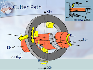
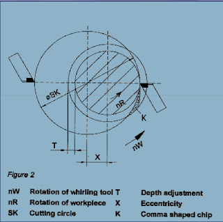
Thread whirling is a process for producing threads in which the whirling cutter, featuring a number of cutting inserts, is run at high spindle speeds synchronous to the material being whirled. It is ideal for difficult materials and thread profiles. Typical cutter speeds reach 6,000 – 8,000 rpm, while the material being cut is run at much lower speeds (10-60 rpm). The pitch angle of thread is determined by the helix angle of the cutter.

Reduced “pounding” on the cutter is a primary benefit of the whirling process as the cutting insert eases into and out of the cut, producing a comma shaped chip. The eccentric cutter path radius coincides with the work radius at the minor diameter, yielding very good roundness.

Those accustomed to single pointing threads will see clear benefits in thread whirling. The whirling process produces very manageable “comma” shaped chips rather than long stringy chips. Pre-turning of the bar is not required and the whirling head is continually in the cut. Shorter cycle times are the result. Finally there are no issues with deflection when cutting long parts because the guide bushing acts as a support for the bar.

When compared to milling threads, whirling produces a number of the same benefits relative to cycle time. In addition to those, manufactures will appreciate the smooth rounded surface produced by whirling. Milling cutters produce a pounding action and leave the surface of thread faceted.

At the end of the day, the following things can be said about the thread whirling:
  1. It produces surfaces finishes similar to grinding
  2. It delivers better surface integrity than milling
  3. It is faster than single point threading
  4. Offers better chip control than single point threading
  5. Better cycle times on longer threads result